We installed 5.94kW of solar PV in late 2017, with an ABB PVI-6000TL-OUTD inverter, and also a nice energy efficient Sanden heat pump hot water service to replace our crusty old conventional electric hot water system. In the four years since then we’ve generated something like 24MWh of electricity, but were actually only able to directly use maybe 45% of that – the rest was exported to the grid.
The plan had always been to get batteries once we are able to afford to do so, and this actually happened in August 2021, when we finally got a single 10kWh Redflow ZCell zinc bromine flow battery installed. We went with Redflow for several reasons:
- Unlike every other type of battery, they’re not a horrible fire hazard (in fact, the electrolyte, while corrosive, is actually fire retardant – a good thing when you live in a bushfire prone area).
- They’re modular, so you can just keep adding more of them.
- 100% depth of discharge (i.e. they’re happy to keep being cycled, and can also be left discharged/idle for extended periods).
- All the battery components are able to be recycled at end of life.
- They’re Australian designed and developed, with manufacturing in Thailand.
Our primary reasons for wanting battery storage were to ensure we’re using renewable energy rather than fossil fuels, to try to actually use all our local power generation locally, and to attain some degree of disaster resilience.
Being in Tasmania, most of our grid power is from renewable sources anyway (hydro), so the renewable energy argument may seem a little weak at first, unless you cast your mind back to the time some idiot decided to deplete our dams by selling a whole lot of hydro-generated power to Victoria in an El Niño year, then the Basslink cable broke and Tasmania had to fire up a bunch of diesel generators to get through winter. Good times.
On the local generation and use front, as I mentioned at the start of this post, we’ve previously exported more than half the energy we generated, but the feed-in tariff we get from Aurora (the power company) is only $0.06501 per kWh. Compare that to the rate we pay for grid energy ($0.29852/kWh peak or $0.139/kWh off-peak). Say we exported 13.2MWh in the last four years, we would have received about $858 worth of credit… But then when we drew power back from the grid at night, or on cloudy days, we would have paid somewhere between $1834-$3940 for that same amount of power. Treating the grid as a proxy for battery storage does not make any sort of financial sense.
As for disaster resilience, we don’t often have grid outages, but we do have them, and that can be a problem. Notably, all our potable water comes from rainwater tanks attached to the house and shed, and the pumps that push that water to the taps are electric, so if the grid is down we don’t have running water. Sure, I can get water out of the tanks with a bucket or a jug, and that’s fine for a little drinking or handwashing, but it’s not good long term. Then there’s our fridges and freezer – at any given time we’re likely to have a lot of stored frozen meat from animals we farm. We don’t want to lose that in a potential extended grid outage, as could happen in bushfire season or during a severe weather event. Also, it’s nice to still have power for our local network and NBN kit, so we can check the TasNetworks Power Outages page to find out WTF is going on.
Complete grid independence would be nice, and with our current power utilisation and a single Redflow battery we could almost do it in the height of summer, or even on some good days in spring or autumn, where we can generate all we need to run the house during the day and charge the battery to 100%, then draw it down overnight. The kink is that Redflow batteries need to undergo a maintenance cycle at least every three days where they are completely discharged for a few hours. If you’re grid connected you don’t really notice this, because the maintenance cycle commences at sunset and once the battery is drained you’re just using grid power again until the sun comes up, but it does mean we can’t be grid independent even if we theoretically have enough PV generation to do so, until we get a second battery (with more than one ZCell, the maintenance cycles are interleaved so at least one battery will always have some power in it).
The other problem with grid independence is that as much as Tasmania is excellent for solar PV generation in summer, it sucks in winter. Looking at our generation and usage figures for 2019, from mid-May to mid-August we were only able to generate 17% of the power we used, and I’ve seen days where we only generated 1-2kW in the entire day. Compare that with summer when we’ve peaked above 40kW some days in December.
Still, if the grid went away for a long time in the warmer half of the year with our current setup, it’d be irritating every few nights, but I reckon we’d manage OK. Of course, there would be some adjustments required to minimise our utilisation: I’d set the blockout timer on the Sanden so the hot water only heated during daylight hours, I’d turn most of our computer equipment off overnight, we’d try to avoid using the microwave at the same time as any other chunky electrical appliance so as not to pull more than 3kW continuously from the ZCell, there’s some lights we usually leave on that we’d just turn off, and so forth. In the colder half of the year, well, I guess we’d try to eat all the frozen food quickly then limp along as best as possible. We would still have some power, some of the time.
When we originally had the PV installed, it was AC coupled, i.e. the solar panels were connected to the inverter, and the inverter was connected to the grid, along with our loads. Our choice of inverter (ABB) was partly because it was Selectronic certified, and at the time we knew Redflow to be working with Selectronic battery inverters. Once we finally got to contacting Murray Roberts from Lifestyle Electrical Services in order to get a quote and talk about installation, circumstances had changed. It turns out that the Selectronic kit just doesn’t like flow batteries with their need to be completely discharged periodically. Victron Energy gear on the other hand works really well with – and is fully supported for use with – Redflow’s ZCell batteries. Lesson learned: with changing technology it doesn’t always pay to plan too far in advance.
Murray initially proposed a setup which would have hooked straightforwardly into our AC coupled solar, i.e. the ABB inverter and PV cells would remain connected as is, then there’d be a Victron energy meter to measure what was coming from the PV and from the grid, a Victron MultiPlus II inverter/charger to charge the battery and pull from the battery to run some loads, plus a Victron Cerbo GX and GX Touch to provide monitoring and control. Some of our power circuits to the house would be hooked up as Essential House Loads (i.e. to be supported by the battery during a grid outage), and some would be Non-Essential House Loads, i.e. powered by the grid and/or PV, but without battery backup. The Victron Cerbo GX and the Redflow ZCell Battery Management System (BMS) are internet connected to hook up with Victron’s VRM portal, which provides handy monitoring tools and graphs, and to allow remote support and assistance and firmware updates. The initial proposal looked something like this:
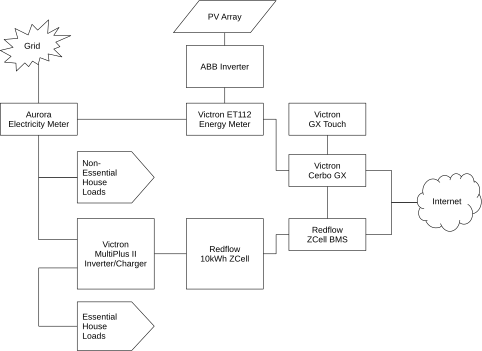
That configuration would have involved the least messing around, and met our goals of:
- Utilising as much of your own energy as possible locally.
- Dealing with occasional/unexpected grid outages (modulo the ZCell maintenance cycle).
But, it still fundamentally relied on the grid. With AC coupled solar, if the grid goes down your inverter automatically goes into anti-islanding mode, and won’t give you any power from your PV array even if the grid is down during the day and the sun is shining on your panels. Your first thought here may be “wait, if the grid is down but I still have sunlight, surely I should still have power”, and that’s an understandable reaction, but anti-islanding is actually a safety feature. If the juice goes from the PV cells to the inverter to the grid and your loads, and you’re exporting power while a power company employee is doing maintenance works on the grid side, you could electrocute them. This would not be a good thing.
A perhaps less obvious problem with this setup is that you can’t black start the site during an extended grid outage. If the grid is down and the inverter is thus in anti-islanding mode, you have no way to get power to restart the system and recharge the battery from empty (unless you’ve also got a generator). “But the grid never goes down for that long…” you might say, until you look at the outages really severe bushfires can cause (think: East Gippsland in the 2019-2020 Black Summer bushfires).
After some further discussion, Murray proposed getting rid of the ABB inverter, and doing DC coupled solar instead, with a Victron MPPT RS hooked up to the PV, two MultiPlus IIs, so that we could handle up to 10kW of power (that’s the maximum limit of all loads and grid export), with all house loads hooked up as Essential, so they can be supplied by whatever combination of grid, solar and battery power is available at any given time. Voilà:
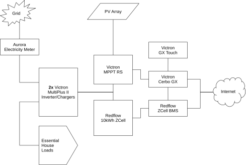
One thing that’s missing in the above diagram is a manual changeover switch we had installed later, so that if there’s ever a fault in the Victron cluster that requires major works, but the grid is still up, we can manually switch all our loads back over to the grid side for the duration. Not that I expect to need that functionality, but better to have it than not just in case.
The 10kW maximum has proven to be fine, by the way – we just don’t ever put anything like that much power through the system at once. During the day we might pull 400-700W continuously with spikes from 1-3kW or occasionally 4-5kW when multiple heavier loads come on. I think the highest we’ve managed was 7kW very briefly one time with a panel heater and the microwave and the hot water and the clothes dryer and gods only know what else was on at the time, the point is it’s not easy to get the load that high. Note that we currently have a gas stove and oven – if we switched that to electric we might want to be a bit cautious about running lots of other heavy loads while cooking, but I suspect we’d still be fine in general.
Rhys, one of Murray’s crew, did a fantastic job of installing all the kit over several days, then Murray came out to do the final commissioning and bring the system online on August 31, 2021. Here’s a couple of pictures:
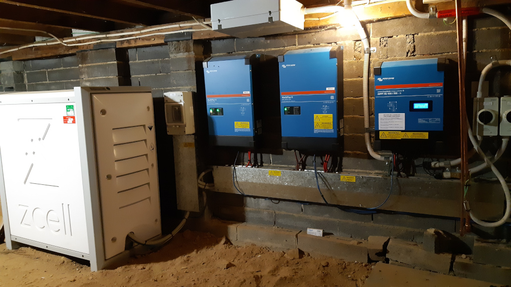
The transparent box in the above photo contains the Cerbo GX and the ZCell BMS, along with a little 12V backup power supply so that those things keep running if the grid fails and the ZCell is at 0% State of Charge (SoC). The ethernet switch above the sub board hooks up to the network point I installed previously when I was using a Raspberry Pi to monitor the ABB inverter’s generation. It’s Power-over-Ethernet, run from a UPS in my office which also keeps the NBN box and router alive, so the whole system still has internet access for about an hour even if all other power sources are dead (handy if there were some sort of fault and we needed remote assistance).
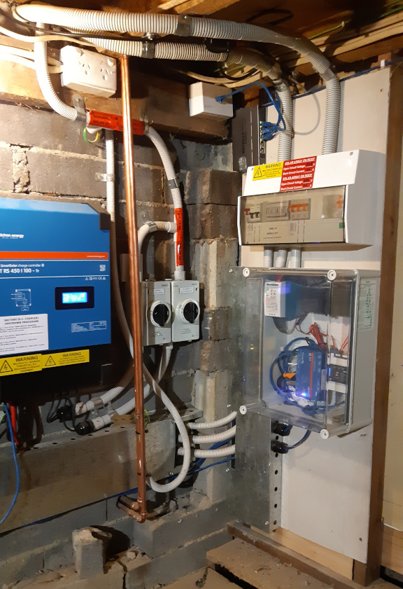
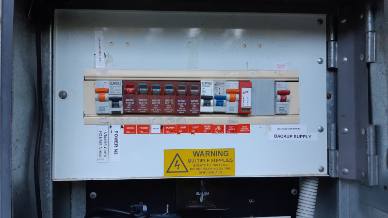
Here’s what the main switchboard looks like now. The leftmost switch (“Main switch (grid supply)”) turns grid power on/off to the sub board under the house, which goes from there to the Multis’ AC input. The AC out comes back up here to the right-hand switch (“Victron Sub Board Backup Supply”) and thence to all the loads (the various switches in the middle).
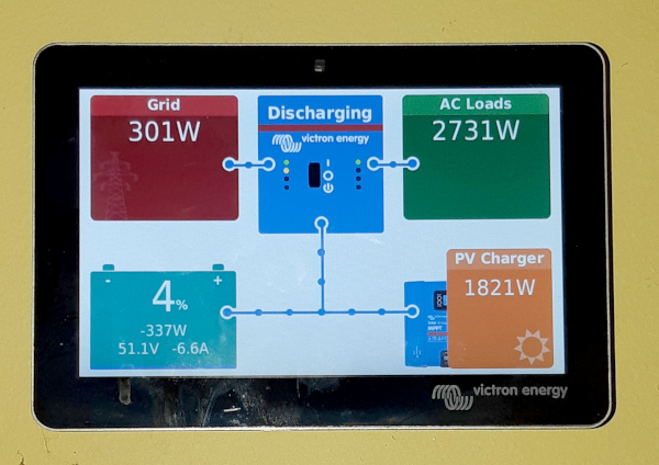
Inside the house there’s a neat little touchscreen console (the Victron GX Touch), which connects via an HDMI cable in the wall to the Cerbo under the house. This shows you what everything is doing at any given time, provides notifications of alarms (e.g.: “Grid Lost”) and has a series of menus for configuring the system. The exact same console is also accessible via a web browser or mobile phone, either over the local network, or remotely via the VRM portal.
Three days after everything was up and running, we went out to run some errands and came back home in the afternoon to discover the Cable PI device in our kitchen beeping like mad. All the power was still on in the house. I called Murray in a bit of a panic thinking something was broken, but it turned out we were experiencing an actual grid outage over a large area – all the way from Grove to Leslie Vale, 802 properties were without power due to wires down in strong wind, and the PV was powering our house. We didn’t feel a thing. The UPS in my office noticed a small dip for a second or two when the grid failed, but the microwave clock was still on, and other computer gear not hooked up to a UPS remained up during the cutover. And the battery kept on charging – it was at 65% SoC when the grid went out and up to 83% by the time the grid came back.
This was just awesome.
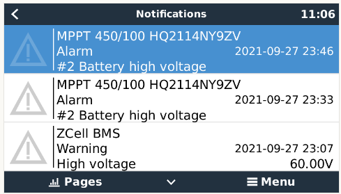
A few days after that, suddenly, at 19:39 on September 6, we were without power. The grid was up, but the Victron kit had shut down. This was not awesome. It happened during the ZCell’s regular maintenance cycle, and at the time we got a warning in the BMS logs, and a battery high voltage warning from the MPPT. It was unclear then exactly what the problem was though – our MPPT RS was a newer model so maybe it was different somehow from what had been previously tested? Also, we discovered the DVCC setting still needed to be turned on, so maybe that was the issue. Anyway, I power cycled the Victron kit and everything was fine again until a couple of weeks later on September 19, when the system shut down again during a maintenance cycle, and again coinciding with battery high voltage warnings.
Because of the previous shutdown, Murray had been in contact with Simon Hackett from Redflow, and Simon subsequently enabled the “DC-coupled PV – feed in excess” setting. The assumption here was that the extra power being delivered from the ZCell during the maintenance discharge wasn’t absorbed by our house loads, i.e. it was trying to discharge at 1kW, but our loads were utilising less than that, and there was nowhere for the excess to go, hence the shutdown. Enabling “DC-coupled PV – feed in excess” allows power from the DC bus to be sent to the grid if necessary, which turns out to be the case at our site. A second ZCell would mitigate this because the one under maintenance would simply be able to dump to the other (assuming it wasn’t already full), but we only have one battery so far.
At this point, after those two final settings changes (and a firmware update) the system was operating exactly as it should. Everything was configured correctly, and we could survive grid outages if there was charge in the battery and/or the sun was up. Our electricity meter was replaced on September 21 so we could switch to Tariff 93 Peak & Off-Peak billing. There were no further unexpected shutdowns. Everything was totally fine, except we were still seeing these weird battery high voltage warnings during the ZCell maintenance cycle, reported by both the BMS and the MPPT.
This is something neither Murray nor Simon had seen before. What followed was several weeks of troubleshooting and analysis, which I found absolutely fascinating.
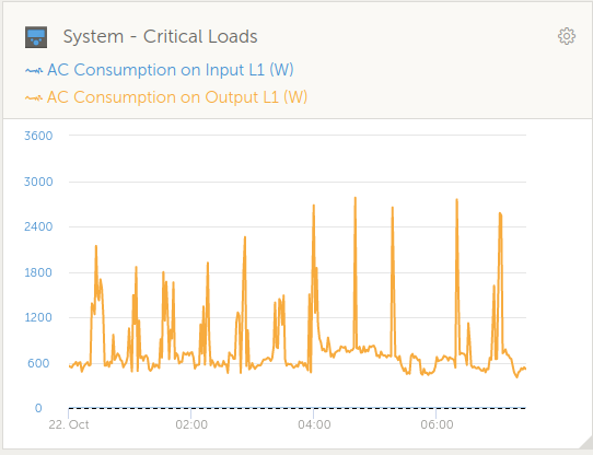
I was keeping detailed notes of what happened during each maintenance cycle, and what I saw in the BMS logs, and on the Cerbo console. Several maintenance cycles later I discovered a correlation between the battery high voltage warnings, and sudden large changes in AC loads, notably when a 2400W panel heater in our bedroom turned itself on and off overnight. Also, the high voltage warnings seemed to be more likely to occur if we went into maintenance with a high state of charge, versus a low state of charge.
Simon, who knows and understands how the ZCell behaves during maintenance, explained about the Energy Extraction Device, which is part of the unit whose purpose is to deliberately drain the battery down to zero for maintenance in a timely fashion. He wondered if there was some issue where very high power demands at short notice, while the the EED was active, were causing the DC bus voltage to fluctuate and in turn cause the MPPT to respond in an unusual manner. We experimented with changing settings on the BMS to activate the EED later than usual in the maintenance cycle (“Start maintenance when SoC below x%”), and also experimented with limiting inverter output on the Multis, and tweaking the maximum charge voltage.
After a few more cycles of observation, the suspicion became that the MPPT itself wasn’t at fault, rather it was just being the messenger. Maybe these odd voltage spikes had always happened at other sites too, but the new MPPT RS units were doing a better job of noticing them?
Later in October, Simon noticed that we were seeing spikes very close to when the battery was nearly completely empty. At that point in time, the EED was telling the Multis that it had a 10 amp output capacity, but if the Multis tried to draw on that to handle a sudden rise in load (as from our panel heater for example), the battery voltage would collapse, and the system would oscillate a bit between those two states. That behaviour was fixed with a small firmware change which I believe later landed in the BMS 1.1.11 release. Unfortunately, that change by itself didn’t make the high voltage warnings go away.
A few days after that, we suddenly had a slew of #201 – Internal DC voltage errors from the MPPT, so we were back to being concerned that maybe there was something wrong with that piece of equipment, especially given those errors began to crop up more often as time passed.
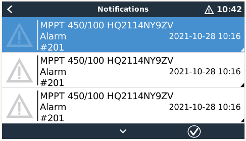
Victron’s documentation ominously stated that this error meant “a measurement circuit inside the unit is broken” and the unit “is really broken, not safe for use, and if it hadn’t stopped working already then it would have stopped working soon”. Clearly a replacement or repair was in order, but I’ll get to that later.
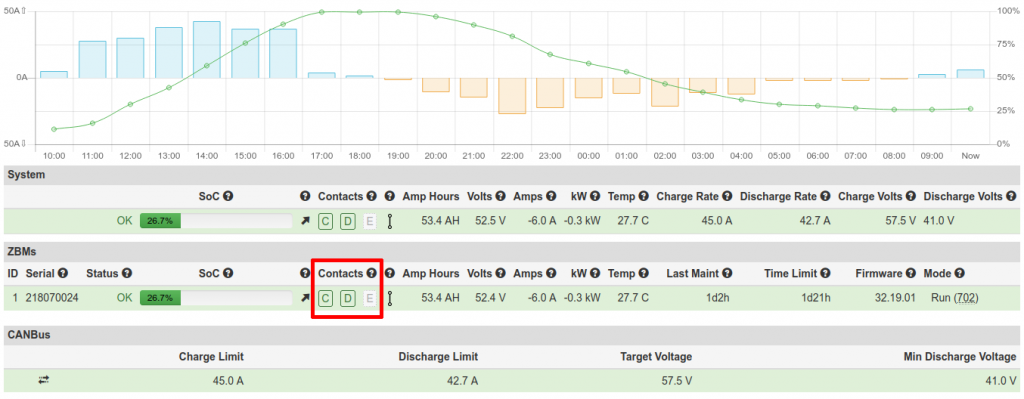
On November 4, looking at the logs I’d collected from November 2, Simon noticed that one of the high battery voltage warnings happened at quite a high state of charge (72%), which meant it wasn’t really about the battery running out of energy and having the voltage collapse. It looked like it was the EED being over-drawn, regardless of how much energy was still in the battery. It turns out there’s a thing that the ZCell does to handle surge demand when the EED is on, called an “EED switchback”. ZCells internally have three contactors, for Charge, Discharge and EED (also known as Strip). In normal operation, the C and D contactors are on, and E is off, so the battery can be charged or discharged at will, and the EED is doing nothing. During maintenance, the EED comes on, but it can’t deliver more than 20 amps. If the site pulls more than the EED can supply, the battery goes back to normal operation (C and D on, E off) while the high demand is present. Once the high demand goes away, it switches the EED back on, to keep discharging at the normal rate of 1kW. But, by default, that switchback process only happens five times per battery maintenance cycle so as to avoid the potential for excessive cycling of the contactors in weird edge cases.
Looking at our overnight load with the panel heater on, there’s loads of spikes from below 1kW to above 1kW, so we were getting through that switchback limit very quickly. After that, with the high load from the panel heater, it was entirely possible that the Multi cluster would try to pull more power than the EED could provide, and the EED would shut down in response, resulting in weirdness on the DC bus. Simon’s suspicion for why this hadn’t been seen before was that it needed at least four casual factors to be present at once:
- Site demand is spiky for the entire night.
- The spikes start below 1kW and end above 1kW to use up the switchback quota.
- The site has only one battery (if a second battery were present it would handle the surge load while the first was in maintenance).
- The two Multis are capable of running far more load than the battery can service.
If we were to change or remove any one of those factors, we wouldn’t see the problem. So, as a test, Simon changed the switchback limit from 5 to 50, and I watched what happened during the next maintenance cycle. The status page of the BMS web interface shows, among other things, the current state of the contactors. Here’s an example with C and D on, and E off:
The ZBM logs also show the contactor state over time. Here’s a snippet I’ve colourised to make the state changes obvious:
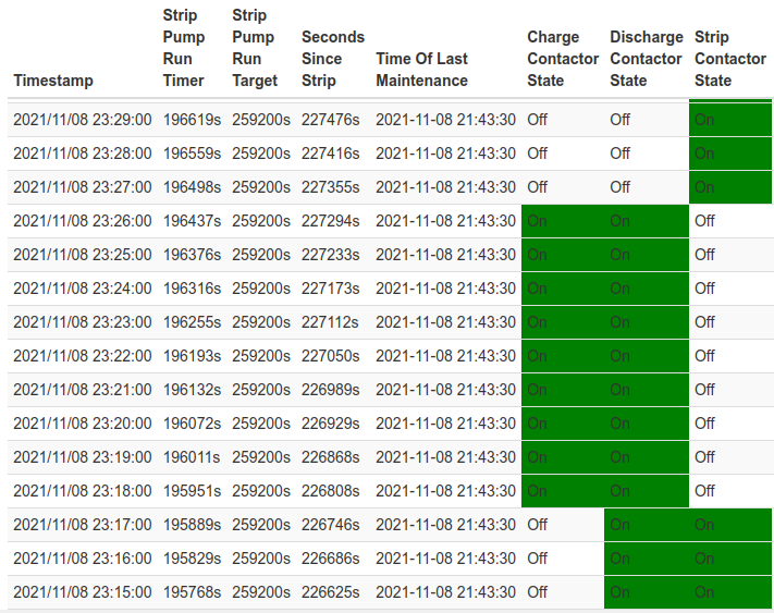
If we take the above section of ZBM logs from 2021-11-08 23:15 to 23:29, it looks like we had “_ D E” up until 23:17, then switched to “C D _” from 23:18 to 23:26, then finally to “_ _ E” at 23:27. Based on this I’d imagine we had one switchback event that lasted eight minutes. But I had earlier noticed on the status page that the contactors seemed to be toggling more rapidly, so I wrote a little script to scrape the BMS REST API once per second and dump that to a file, which shows Charge and EED toggling on/off about ten times in that window:
2021-11-08T23:14:28+11:00    "_ D E"
2021-11-08T23:17:59+11:00    "C D _"
2021-11-08T23:18:29+11:00    "C D E"
2021-11-08T23:18:34+11:00    "_ D E"
2021-11-08T23:18:56+11:00    "C D _"
2021-11-08T23:19:14+11:00    "C D E"
2021-11-08T23:19:20+11:00    "_ D E"
2021-11-08T23:19:54+11:00    "C D _"
2021-11-08T23:20:17+11:00    "C D E"
2021-11-08T23:20:18+11:00    "_ D E"
2021-11-08T23:20:49+11:00    "C D _"
2021-11-08T23:21:19+11:00    "C D E"
2021-11-08T23:21:22+11:00    "_ D E"
2021-11-08T23:21:46+11:00    "C D _"
2021-11-08T23:21:51+11:00    "_ D _"
2021-11-08T23:21:54+11:00    "C D _"
2021-11-08T23:22:23+11:00    "C D E"
2021-11-08T23:22:26+11:00    "_ D E"
2021-11-08T23:22:43+11:00    "C D E"
2021-11-08T23:22:45+11:00    "C D _"
2021-11-08T23:23:26+11:00    "C D E"
2021-11-08T23:23:30+11:00    "_ D E"
2021-11-08T23:23:43+11:00    "C D _"
2021-11-08T23:24:30+11:00    "C D E"
2021-11-08T23:24:34+11:00    "_ D E"
2021-11-08T23:24:43+11:00    "C D _"
2021-11-08T23:25:35+11:00    "C D E"
2021-11-08T23:25:39+11:00    "_ D E"
2021-11-08T23:25:49+11:00    "C D _"
2021-11-08T23:26:40+11:00    "C D E"
2021-11-08T23:26:44+11:00    "_ D E"
2021-11-08T23:26:49+11:00    "_ _ E"
On the assumption we were hitting way more switchbacks than expected, Simon just went and set the maximum switchback count to 999. A few days later, taking the log from my script, I saw something like 150-160 switchbacks, but given we’d set the limit way high, that fixed all the high voltage warnings, except for one, right at the very end of the maintenance cycle when the discharge limit from the ZCell drops from 10 amps to 0 amps.
Simon discussed this final spike with the folks who built the EED, and found that when current draw from the EED stops, there is a voltage spike, of very low energy, for 10ms, and it can rise as high as 64V during that period before dropping back to the expected 57V. It’s normal for the EED to do this, and as there’s no real energy in it, it won’t be damaging anything. The thing about our site seems to be the new MPPT RS, with a new voltage sensing circuit that’s actually capable of noticing the spike, whereas the other gear (the MultiPlus IIs) misses it because it’s so short. The advice from the electrical engineer was to try adding more capacitors on the DC bus to absorb the spike. We already had two 47,000uF capacitors on there, so Murray went and ordered two more.
With the high battery voltage warnings out of the way, we were back to the #201 Internal DC voltage errors from the MPPT. On the assumption the unit was indeed faulty in that regard we requested a replacement, but Victron came back and said the problem could be fixed by replacing two resistors on the main board of the unit. I guess that makes sense – if you can fix a problem with $2 worth of resistors, that’s three orders of magnitude cheaper than replacing the whole unit.
By then we were getting into December, and what with pandemic-related shipping delays and the Christmas holiday period, it was later in January before we were able to get the additional capacitors installed on the DC bus, and replace the resistors in the MPPT’s voltage sensing circuit. The additional capacitors went just fine, the replacement resistors not so much. Once the MPPT was powered back up it claimed there was zero volts coming from the PV, even though the sun was shining, and the LCD display started flickering strangely. Something was definitely broken here, so we powered it back down, and Simon arranged for a replacement unit to be sent out, which took another few weeks, which is a damn shame in January/February, being prime solar PV generation time.
The delay did however allow me to spend some time messing around with scheduled charges to see if there was a cost benefit to grid-charging the battery during off-peak times, then drawing it back down during peak, because the reality is we’re going to want to do this in winter when there’s not much sun, so why not try it out in advance? TL;DR: Yes, it’s worth grid charging the battery off-peak, provided you use all that power during peak times, but it’s a bit irritating trying to figure out exactly what you’ll save. In one of my tests it was the difference between paying $3.85 for about 20kWh of usable electricity in a 24 hour period versus paying $4.70, so it’s not insignificant.
Rhys came out and installed the replacement MPPT on February 11, and was done by the middle of the day. Everything was running beautifully again, but when the unit came online there were ten instances of the dreaded #201 Internal DC Voltage Error, along with a #27 Charger Short Circuit. I used the VictronConnect app on my phone to see if I could get any more information directly from the MPPT. It told me there was a firmware update available from v1.05 to v1.08, so I went looking for information about that, and discovered that Victron’s error code documentation had been updated since I first saw it back in late October. In addition to the ominous warnings about broken measurement circuits it now also said:
“Make sure to update the firmware to at least v1.08, in previous firmwares the limits were too strict. And it could trigger falsely during MPPT start-up in the morning and MPPT shutdown in the evening.”
So I updated the firmware, and writing this now, two and a half months later, we’ve not seen a single #201 since. Could this have always been a firmware issue? Maybe, given the “accepted answer” on this Victron Community forum post says that firmware version v1.08 “solves the vast majority of MPPT RS, and Inverter RS, Error 201 issues”. Or maybe it was both – maybe we had a broken bit of kit and broken firmware too. Either way, it’s fixed now.
I continued to monitor regular maintenance cycles, and also deliberately forced maintenance a couple of times with a high state of charge to try to stress it as much as I could. During those periods I saw something like 3-10 switchbacks, so Simon set our switchback limit back down from 999 to 30. I understand a future Redflow firmware update will change this default for everyone to somewhere between 25-50, and I’m very happy that this unexpected testing at our site resulted in firmware improvements that will presumably benefit other ZCell users too.
By late April we’d been through 33 maintenance cycles since the extra capacitors went in, with 26 of those occurring since the new MPPT was installed. There had been only three occasions when the BMS briefly noticed alleged high battery voltages in that time. The MPPT was completely silent until April 20 when we got three battery high voltage warnings within an 8 minute interval right at the end of the maintenance cycle, when the battery was almost completely empty. But the weather had also started to get cold, and those errors coincide with a spike from our panel heater, which is consistent with our earlier observations about load spikes with the EED on being “difficult” and really just points to replacing the panel heater with a heat pump. Heat pump are way more energy efficient, have much smoother load, and can also be used for cooling in summer (they’re called “reverse cycle air conditioners” on the mainland).
That’s about the end of the story. The system is brilliant, and we could not be happier with the support we’ve received from Simon at Redflow, who’s been extremely generous with his time and knowledge, and Murray and Rhys of Lifestyle Electrical Services. Thanks for everything guys, I’ve learned a lot. In the eight months the system has been running we’ve generated 4631kWh of electricity and “only” sent 588kWh to the grid, which means we’ve used 87% of what we generated locally – much better than the pre-battery figure of 45%. I suspect we’ve reduced the amount of power we pull from the grid by about 30% too, but I’ll have to wait until we have a full year’s worth of data to be sure. We’ve also survived or shortened at least five grid outages with durations from a few minutes to a few hours.
The next thing to do is get a second ZCell, and possibly eventually think about a third. Given our current generation capability, two ZCells would allow us to store and utilise 100% of our generated power locally. We’d also have the ability to handle grid outages at any time, because with two batteries the maintenance cycles interleave and they can be configured to always ensure there’s a minimum amount of charge somewhere. A third would allow us to look at Standby Power System (SPS) mode where one battery is fully charged, then put into hibernation where it can remain for months. This sounds like a great way to have backup storage available for grid outages in the middle of winter when there’s no sunlight.
Appendix A – Settings Worth Messing With
Scheduled charging on the Cerbo GX console
In summer I scheduled charges of the battery to 15% between the hours of 04:00 and 08:00, and 30% between the hours of 15:00-17:00. Peak electricity hours during daylight savings are 08:00-11:00 and 17:00-22:00, and I found that a 15% charge overnight from the grid was enough to have a bit in the battery for the morning peak before the PV really got going. The afternoon charge was there mostly just in case we had a cloudy day – we’d usually get way more charge than that from the sun anyway. Now that we’re off daylight savings, peak hours change to 07:00-10:00 and 16:00-21:00, so I’ve set it to a 30% charge from 03:00-07:00 and a 50% charge from 14:00-16:00, which seems to be about right given our general peak utilisation and decreasing sunlight. I’m unlikely to set the afternoon charge higher than 50% because I don’t want to potentially go into a maintenance cycle with the battery very full, but I may re-evaluate that as we get deeper into winter.
It’s worth mentioning that during a scheduled charge, the power will come from wherever the Victron gear can find it, so if the sun is shining, you’ll be charging from the PV, not the grid. One thing to note is that during the scheduled charge period, the battery will not be used to support loads, even if it’s currently got a higher SoC than your limit. Some power will trickle away slowly though, I assume to run the pumps and supporting electronics of the battery itself.
My choice of timing for the overnight charge (four hours up to the start of the morning peak) is me wanting to have some power in the battery for as long as possible overnight in case of outages, without potentially interfering with maintenance cycles, which typically will have finished some time in the wee hours.
I also set up a 15% charge on weekend mornings. This doesn’t save us any money at all (actually it’ll be costing us a couple of tens of cents) because weekends are all off-peak power. The reason is again to have some opportunistic grid backup. Before I set this up we had an outage at 07:45 one Saturday morning with the battery empty, and had to wait until about 09:30 for the PV to bring the battery up to 10% again before everything came back online. Still, that then got us through the remainder of the grid outage which finished at about 10:15.
Battery Maintenance Settings on the ZCELL BMS
On the Battery Maintenance screen of the ZCell BMS, I’ve got “Immediate maintenance for batteries with an EED” turned off, and “Start Maintenance When SoC Below 25%” enabled. This is to try to reduce the amount of time the EED runs, to limit switchbacks caused by our spiky load. In summer I also set “Daily SoC Limit Before Maintenance” to 50%, so the battery would not let itself be charged more than half way on those long hot days with late sunsets and early sunrises. This was to minimise maintenance cycle time, because I’d previously seen occasions where we went into maintenance with 100% SoC, and the cycle didn’t finish before the following morning when the sun came up. I also had a couple of times where I guess some timeout expired and the ZCell went into its final chemical maintenance state while it still had a few percent of charge. Not letting it get very full on maintenance days avoids these situations. Now that we’re getting towards winter I’ve removed that limit because the nights are longer and I expect our evening power utilisation to be higher, i.e. we should naturally use up whatever power we’re able to generate in plenty of time during winter maintenance cycles.
It’s also worth checking the latitude and longitude are set correctly on the Site Configuration page, because that’s how the BMS figures out when the sun sets and thus when to start maintenance by default.
Appendix B – VRM Portal
The VRM portal is a remote monitoring and management web interface which Victron provides gratis for users of their hardware. It provides a realtime view of the same live utilisation information you can get from the Cerbo console, plus handy graphs of solar, grid and battery consumption.
It also provides detailed graphs of just about anything you can think of from any of the system components. It’s extremely useful. Without this I never would have been able to correlate the battery high voltage warnings with load spikes and changes in the ZCell discharge current limits.

The data for the advanced graphs is stored for at least six months, and the solar yield and consumption data is stored for at least 5 years. The alarm logs don’t hang around that long – I suspect it may just be showing the last 1000 entries. Somewhat irritatingly, most of these are usually low battery alarms that we don’t care about (you see a lot of them during maintenance cycles).
Appendix C – Security / Connectivity / Internet Access
The ZCell BMS and Victron Cerbo GX both need to be connected to the internet for firmware updates, remote support, and to work with the VRM portal. They don’t need to be connected 100% of the time, but they do want the connection for those reasons. The system will operate just fine if the internet is down though, and you don’t have to use the VRM portal if you don’t want to. I’ve put everything on a separate network, so I can access the BMS and the Cerbo console from my desktop/laptop/phone, but the BMS and Cerbo can’t do the reverse. It’s not that I don’t trust Redflow or Victron, it’s just sensible to keep systems that allow any form of remote access isolated from the rest of your internal network.
The BMS and Cerbo both provide WiFi APs for initial configuration. I’ve since turned those off. I can use the wired connection to the BMS to turn the WiFi back on if I ever need it, and I can do the same for the Cerbo from its console.
The Cerbo and MPPT both speak Bluetooth, so you can use the VictronConnect app to talk to them from your phone, to view status and update firmware.
Appendix D – Hackability
The ZCell BMS has a REST API, which is documented in the online help available from its web interface. This is how I was able to write a few scripts to log the battery state of charge, the contactor state, and the voltage and warning indicator status:
A bunch of Victron stuff is open source, notably Venus OS, which is the software that runs on the Cerbo. It looks fairly straightforward to get root on these things. It’s also possible to hook up the Victron kit to Home Assistant. I haven’t tried actually doing any of these things yet myself.
Appendix E – Aurora Plus
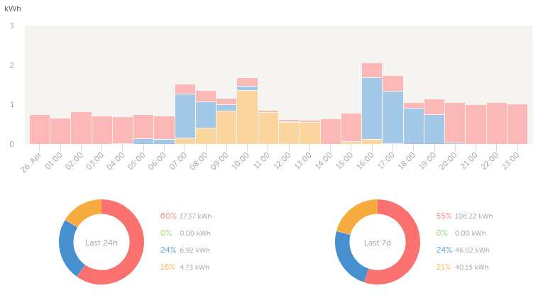
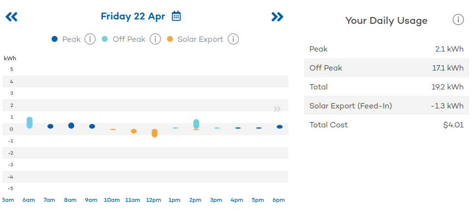
Having switched to Tariff 93 and gotten a fancy new electricity meter, we were able to use the Aurora Plus service from the power company. This provides a web interface and mobile phone app for viewing your power usage down to the hour, colour coded to indicate peak and off-peak usage and solar feed in. You also get a monthly, rather than quarterly bill. This all sounded pretty neat, so I signed up.
Aside from having used it to confirm that the figures I get from the VRM Portal and the power company actually match, it’s turned out to not be especially great.
While the electricity meter records usage information every 15 minutes, it’s only sent back to Aurora once per day, so the usage data is never actually live. Sure, you can see history, but this is useless for adjusting your power consumption on the fly. Compare that with the VRM Portal or Cerbo console, where I can see at a glance how much power is being used and how much solar is being generated right now and decide to turn appliances on or off appropriately.
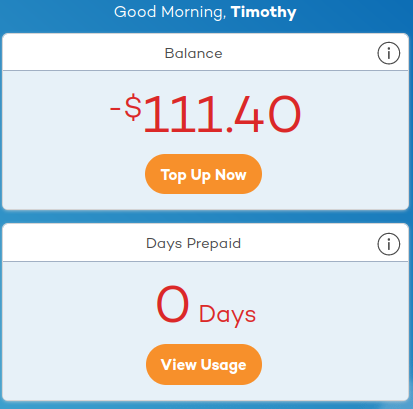
Also, it nags you to give them money. It’s continually telling me I have a big red negative dollar balance, and periodically notifies me to “top up now to get ahead of your monthly bill”. No. I will pay the bill by the due date listed on the bill, after the bill actually arrives.
Finally, it costs eleven cents a day for the privilege of having the service. Under the circumstances I think I’m going to cancel it and just go back to quarterly billing.
Update 2022-06-17: I never got around to cancelling (you can’t do it online – you actually have to call and speak to someone), but I just received a notification saying “From 1 July 2022 you will no longer be charged 11c/day for aurora+”, so I’ve decided to keep it.
Hi Tim
thanks very much for this intriguing detailed story of your Redflow install.
Ray
My pleasure, Ray. I’d been accumulating all these notes about everything so figured I should share the story for posterity 🙂
Truly wonderful, thanks very much. Close enough to where we are, sans Redflow batteries atm.
Just one query, you wrote under the second pic, “The transparent box in the above photo contains the Cerbo GX and the ZCell BMS,”
Was the ZCell BMS relocated for convenience of physical access or other reasons?
The BMS needs to be connected to the Cerbo, and both devices are powered off a little 12V backup power supply, so I guess it made the most sense to place all those components together. Here’s a closeup photo: