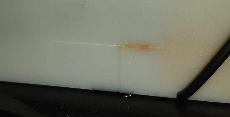
On the evening of September 3, 2025, there was suddenly a strong and remarkably unpleasant flat metallic odour in our master bedroom and ensuite. We opened all the doors and windows and got the fan on, and eventually it went away. The smell didn’t come back after closing up, but the next morning when I was inspecting the Redflow ZCell battery in the crawl space under the house I discovered a 6cm long crack towards the right hand side of the back of the electrode stack, about 2.5cm above the base. A small amount of clear liquid was leaking out.
Due to the way our house is constructed on a hill, the master bedroom, walk in robe and ensuite on the lower floor share some airflow with the crawl space under the main floor of the house. For example, the fan in the ensuite vents to that space, and I’ve felt a breeze from an unfinished window frame in the walk in robe, which must be coming from the space under the house. I’ve since siliconed that window frame up, but the point is, the electrode stack split, the battery was leaking, and we could smell a toxic fume in the bedroom.
Readers of the previous post in this series will be aware that Redflow went bust in August 2024, and that our current battery was purchased from post-liquidation stock to replace the previous one which had also failed due to a leak in the electrode stack. When the new unit was commissioned in March 2025 I applied some configuration tweaks in an attempt to ensure the longest lifespan possible, but it lasted slightly less than six months before this failure. Not great for something that was originally sold with a ten year warranty.
Under the circumstances I wasn’t willing to try to procure yet another new ZCell to replace this one, but given we’d found the leak very early this time, I figured I had nothing to lose by trying to repair it. I had heard of marine fibreglass being used successfully in one other case to repair a leaking ZCell, so I discharged the battery completely then set to work patching it up the following weekend. This involved:
- Wearing PPE (gloves, a respirator, safety glasses)
- Turning the DC isolator off so the unit wasn’t powered
- Carefully wiping the electrolyte leak away with a rag
- Taping up some plastic sheeting below the stack to keep the rest of the unit clean
- Cleaning the stack carefully with a little methylated spirits
- Roughing up the surface with some 80 grit sandpaper
- Cleaning the stack carefully again with methylated spirits
- Mixing up West System 105 epoxy resin and 205 hardener
- Applying four layers of fibreglass cloth (which is irritating to cut with scissors, by the way) in alternating directions – each layer was wet down with epoxy using a brush then applied to the surface of the stack with a little metal roller
- Crawling out from under the house, unkinking most of the muscles in my body, and having a long hot shower
- Waiting til the day after next for everything to set in case 24 hours wasn’t enough before recommissioning the unit
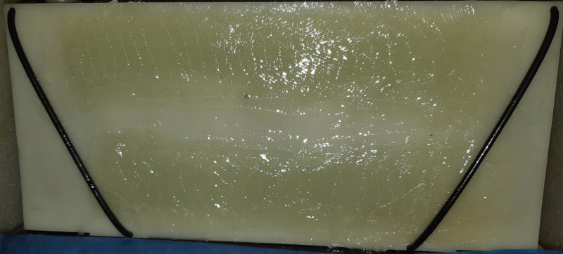
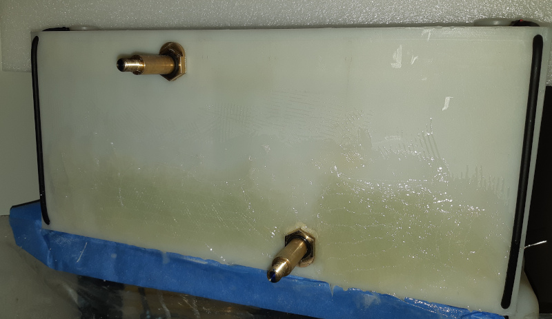
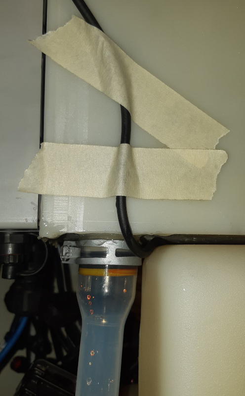
Here’s a picture of the finished repair. I didn’t bother sanding it smooth because it just doesn’t matter – it’s a battery, not the hull of a boat – and I could do without creating any more dust. I actually ran two strips of fibreglass because there was also a little split at the top of the stack, although that one didn’t appear to be leaking.
Recommissioning the unit was interesting. Upon bringing it online, it immediately went into a safe shutdown state because the electrolyte had dropped down from its usual running temperature of 18-24°C to a bit over 8°C during the five days it had been offline.
In order for a ZCell to charge, the electrolyte needs to be at least 10°C, and at least 15°C for it to discharge. So I took one of our 2400W panel heaters under the house and turned it on next to the unit. “How long does it take for a 2400W panel heater to heat 100L of nearby liquid electrolyte by 2°C?” I hear you ask. “Too damn long” is the answer. I started the heater at 13:10, and it was 16:50 before the battery was convinced that the electrolyte was far enough above 10°C to be happy to start charging again. But, charge it did, and we were up and running again… Until the next morning when my wife detected that nasty smell in the ensuite again. Upon further inspection of the unit I found a tiny drip coming from the bottom of the front of the stack, behind the Battery Control Module (BCM). So once again I discharged and decommissioned the battery in preparation for repair.
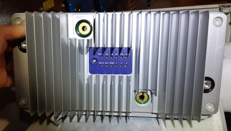
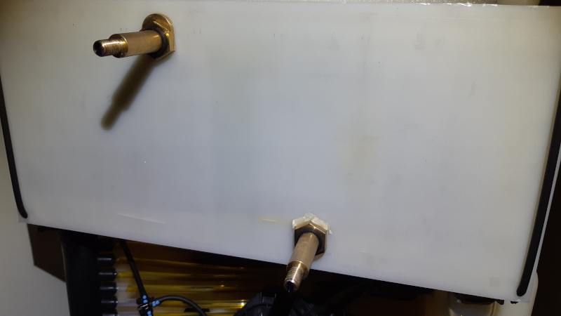
This time I had to pull the BCM off to get to the electrode stack behind it. First I checked that the battery really was discharged with a multimeter. Then I disconnected the DC bus cabling, the comms cable, and the connections to the pumps, fans and leak sensors after taking a photo to make sure I was going to put everything back in the right place. Finally I unscrewed the battery terminals and pulled the BCM off. It’s actually a really neat arrangement – the BCM just slides on and off over the two cylindrical terminals the come out of the stack. It’s a bit stiff, but once you know it comes off that way, you just jiggle and pull until it’s removed.
One thing to be extremely careful of is that you don’t accidentally drop the washers from the battery terminals down into the bottom of the battery, because if you do you will never, ever get them back again, and will have to order some M8 silicon bronze belleville washers from Bronze & Brass Fasteners Pty. Ltd. to use as replacements. I don’t know exactly what Redflow used here, but I know they’re belleville washers from reading the manual, I determined they were M8 by measuring them, silicon bronze is apparently a good electrical conductor, and BABF would let me buy them individually rather than in lots of a hundred. I purchased eight, in order to have several more spares.
There was a bit of cracking on the front of the stack, similar to what was on the back, so then it was a repeat of the earlier fibreglassing procedure. This added a couple of millimetres depth to the front of the stack. Now the circuit board in the BCM could no longer sit flat against the ends of the battery terminals, due to a series of little protrusions on the back of the BCM case which would ordinarily sit flush against the stack. These I lovingly twisted off with a pair of pliers. Then I reconnected all the cabling and used a nice shiny new torque wrench to ensure the battery terminals and DC bus cabling were tightened to 10Nm per the manual.
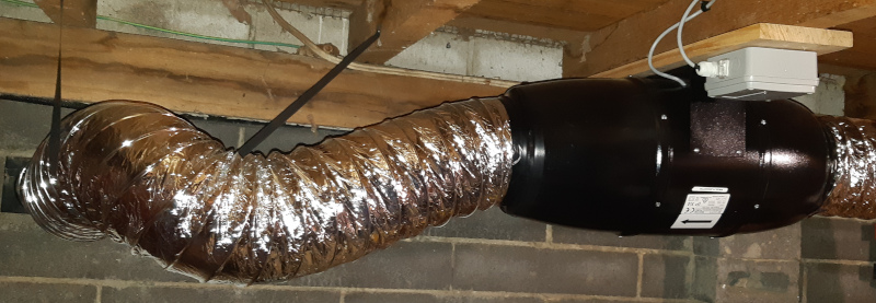
I wasn’t quite ready to recommission the battery yet at this point given we’d had those two nasty fume experiences in the bedroom. If I’d missed anything with this second repair, or if anything else broke and there were gas emissions of any kind, we didn’t want to experience them. So I purchased a sub floor ventilation kit with a bushfire compliant external vent and installed that under the house.
Then in early October (it took a while to get all this work done around my actual job) I brought the battery online again. Of course I had to once more use the panel heater to get it going. We’re running the ventilation fan 24/7 (it’s very quiet), and I got into the habit of going under the house and doing a visual inspection of the battery every morning as part of our daily rounds feeding the chickens.
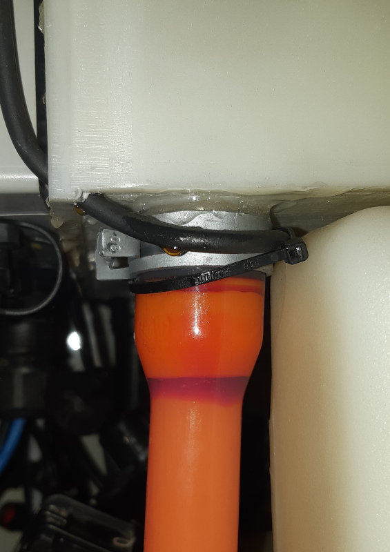
Everything went beautifully until October 29 when I noticed a small drip of red liquid which appeared to be coming from a capillary tube on the front right of the stack. The previous leaks had appeared clear, which I imagine means they were from the zinc electrolyte side of the battery, whereas this red suggested to me a leak from the bromine side of the battery. The electrolyte actually initially has the same chemical composition in both tanks, but charging changes it – you’ll see the electrolyte in the bromine pipe on the front of the battery go orange, then red, as charge increases, whereas the electrolyte visible in the zinc pipe remains a mostly transparent pale yellow. Anyway, another leak meant decommissioning the battery again to investigate.
Off came the BCM again to check my fibreglass work (pristine and undamaged!) and off came the side of the enclosure to get a better look at the problem area. I inspected the capillary tube in minute detail with a magnifying glass and couldn’t find any obvious damage that would explain the leak. The tube runs from the top of the stack down through a hole in the bottom front of the stack, which keeps everything very neat, but honestly seemed to me like it was introducing a potential weak point into the front of the stack, so I rerouted the tube then carefully filled the hole in the stack with Araldite, on the assumption the leak was actually in the stack. In case the leak turned out to be in the tube, I ordered some viton tubing to use as a replacement. After recommissioning the battery again no further leak was evident over several days, indicating that the problem was indeed in the stack, and not in the tube. This is probably just as well, as my new viton tubing turned out to have a slightly smaller internal diameter (2mm) than whatever Redflow used during manufacture – maybe 2.5mm?
A few days after that on November 7, the battery indicated a hardware failure due to “impedance error”, and a small drip of red liquid appeared on the front left side of the stack. I’ve been told this error can be due to higher pH levels and the formation of zinc hydroxide, or degradation of the core electrode, or separator failure, or overheating of the stack reactor. Within the limits of my knowledge and ability there was very little I could do about any of these things, so then the question became: what next?
At this point I felt that I had really pushed things as far as I reasonably could. If the fibreglass repairs on the front and back of the stack proved sufficient and nothing else had gone wrong, I would have been happy to continue operating the battery as we had been since March, but these additional leaks and the impedance error suggested to me that things were going to continue to go downhill. It seems that the answer to the question posed in my last post, i.e. “how far down the road can we kick the migration can” turned out to be about eight months.
The only technology that’s immediately viable for us to switch to is LiFePO4 batteries. We’re looking at a stack or two of Pylontech Pelios because they will work with our existing Victron inverter/charger gear and come in IP65 cases so can be installed outdoors without too much difficulty. It will still be a while before we can get those installed though, and in the meantime I can’t just decommission the existing battery because then our solar generation won’t work.
The way our system is installed, we have solar panels connected to an MPPT on the DC bus, which is connected to the battery, and to our MutliPlus II Inverter/Chargers which in turn power our loads. The ZCell Battery Management System (BMS) tells the system what the battery charge and discharge limits are. If the battery is missing or broken, the BMS will not let the MPPT run at all, which means that no battery = no solar power, not even to power our loads.
I actually tried to work around this problem a couple of times in the past when previous batteries were dead. There’s a description of some unsuccessful attempts in an earlier post, and I also separately tried to fake up what I called a Virtual ZCell in software back in December 2024. In that experiment I was telling the Victron system that there was a battery present at 25% state of charge, but with a charge current limit of 0A (so it wouldn’t try to charge the non-existent battery) and a discharge current limit of 1A (so the battery looked at least a little bit available but no real discharge would be attempted). Incredibly this worked, but after about a week the MPPT started raising various errors so I gave it up. It seems that it’s necessary for a real physical battery to be present in order to help correctly regulate the voltage on the DC bus.
Back to the real battery: After the impedance error occurred I shut it down, rerouted the left front capillary tube, Araldited up its hole and the bottom front of the stack as I had done on the right hand side, then recommissioned the battery and reset the impedance error. I then set the system maximum state of charge limit in the BMS to the lowest value possible (20%). This would mean that the battery would never be charged much, and thus would never be stressed much. I imagined that whatever reactions were happening inside the stack that were causing things to break would happen either less often, or with less severity, or both.
The Araldite repairs were ultimately not completely successful. A teeny tiny red drip or two have since reappeared on the bottom front of the stack, but they are very small drips. I wipe them up every couple of days. The impedance error has not yet recurred. The fibreglass is still solid. We are thus able to continue to use our whole system in some capacity – notably with functioning solar power generation – until we’re able to migrate to those Pelios.
I will continue to write about our system in future, but this post will probably be the last that covers Redflow batteries in any detail. I have included some further observations below in the hope that they will be useful to others such as the Flow Battery Research Collective in their efforts to design and build a viable open source flow battery. I would also like to take the opportunity to express my thanks to Stuart Thomas (another ZCell user) for plenty of helpful advice and interesting discussions over the past year.
Appendix A – Redflow Hardware
There’s an article on the design of the ZBM3 on Simon Hackett’s blog from back in May 2021. Having now spent a fair bit of time physically messing with the ZBM3 myself I’m happy to confirm almost all the good things in that post about about the design of the unit – the whole thing is just much neater and nicer than the ZBM2. The one thing that ultimately didn’t work out with the new design, unfortunately, was improved reliability. Our original ZBM2 lasted from August 2021 to December 2023 – just over two years – before failing due to a leak in the electrode stack. Our first ZBM3 failed after nine months. The subsequent one started leaking after six months and even though I continue to nurse it along, I think we can reasonably treat that one as failed too.
Based on my experience, the reliability issues are all in the stack. Whether that’s a problem with the manufacture of the stack, or chemical reaction issues at runtime, or a combination of the two, or something else entirely, I don’t know. But if those problems could be fixed or mitigated somehow, the rest of the design is quite clever:
- The two electrolyte tanks are side by side, with pumps at the front of each tank.
- The pipes from the pumps run across to the opposite side of the front of the stack, so electrolyte from the left (bromine) tank flows up into the bottom right of the stack, then through the stack diagonally to come out the back left of the stack and down into the top of the bromine tank. The reverse is true for the right (zinc) tank, which comes up into the bottom left of the stack.
- The pipe from the zinc tank has extra long sections of hose that loop around under the stack so that cool air can be blown over them from the fan in the rear of the unit if necessary.
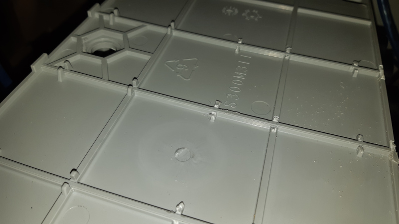
- The catch can – which captures potential gas emissions using activated carbon – sits neatly out of the way in a cavity between the two tanks.
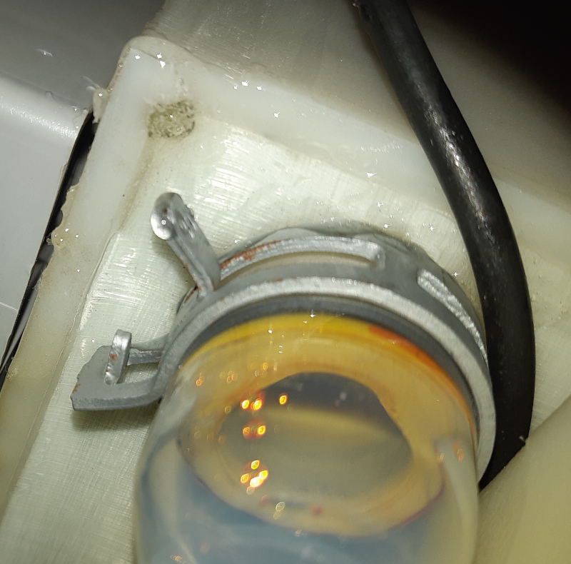
- The electrode stack is just strapped to the top of the tank, so can theoretically be lifted off for replacement by cutting the straps.
- The BCM just slides onto the terminals that come out of the front of the stack as described elsewhere in this post.
- The latest version of the ZBM3 has a screw cap on the front of the zinc tank for easy installation and replacement of the carbon sock.
Nevertheless, in my opinion, there is still room for improvement:
- I’ve been told that if you do actually remove the electrode stack, whatever electrolyte remains in it will spill everywhere. Some sort of shutoff valve or set of plugs might be in order here.
- I have not the faintest clue how one would go about replacing the pumps should they fail, without getting electrolyte all over the place. I imagine you would have to drain the electrolyte first, but how? With some sort of siphon?
- There’s a filter somewhere in the tank which can apparently become clogged. I don’t know how to inspect, clean or replace this if necessary.
- The position of the catch can, while neat, seems to unavoidably result in the hose connected to it being kinked. One of the line items in the annual maintenance checklist specifically says to make sure that hose isn’t kinked, so I pulled my catch can out of its hole and left it sitting horizontally across the front of the unit.
Speaking of the catch can, it’s connected to the zinc tank by a pressure release valve, although the ZBM3 manual erroneously states that it’s connected to the bromine tank. There does not appear to be any pressure release valve attached to the bromine tank, whereas the ZBM2 had a gas handling unit consisting of pressure release valves connected to both tanks (see section 4.7 “Gas Handling Units” in the ZBM2 manual). Is the pressure release really not necessary for the bromine tank with the ZBM3, or is this another source of potential trouble?
The carbon sock, which needs to be replaced annually, is interesting. It looks a bit like a door snake, but it’s filled with some sort of carbon material and sits in the zinc tank. I understand it behaves somewhat like a sacrificial anode, the idea being that whatever corrosion or oxidation that might happen to the carbon in the electrodes in the stack under certain operating conditions, will instead happen to the carbon in the sock.
Another item of annual maintenance is to “check the pH and adjust if necessary”. How, exactly, and to what value? I have recent correspondence which says the pH should ideally be 1.5-2.5 and that it can be lowered by adding hydrochloric acid and running the pumps for a couple of days, but it would be helpful to somehow include a pH sensor in the unit given that mopping up leaks with litmus paper isn’t really very accurate.
As for the stack itself, it looks like a solid rectangular chunk of some sort of fibreglassy material. The front plate appears to be a separate piece that was stuck on somehow, which I assume makes for a weaker spot between that plate and the rest of the stack. This could explain some of the leaks I experienced. Maybe the ZBM2 design with the bolts holding two stacks together really did make for a better seal?
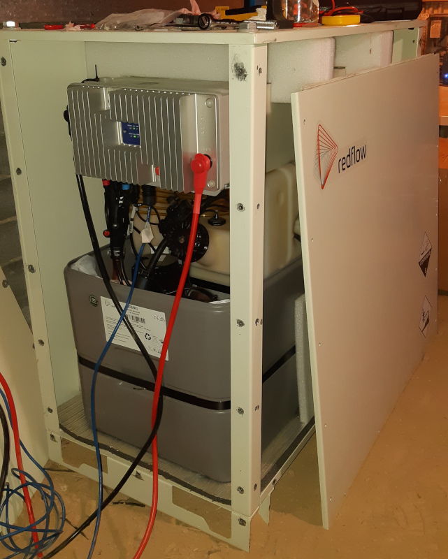
Finally, the most recent enclosure design – a solid metal box with cowlings on each end that allow airflow but not animal ingress – is excellent until you have to do any work on it. Everything is very heavy, and once you remove the screws that hold one of the ends on, everything has a tendency to slip just slightly out of alignment, making it difficult to screw back together, at least for one person. Given the frequency with which I ended up needing to inspect and mess around with my most recent unit, I removed the ends and one side of the enclosure and just left it that way.
Appendix B – Redflow Software
The management and monitoring interface for the BMS is overall decent and easy to use. There’s a main status screen from which you can drill down to get more detail and perform various operations. The included quick start and reference guides are very thorough and cover most of the details, so rather that describing the UI further here I’ve decided to reproduce those manuals in PDF form for posterity:
You can easily get full details of the current state of all connected batteries by browsing the UI, or by hitting the /rest/1.0/status endpoint to dump everything in JSON format. It’s possible to browse the last three months of BMS logs via the UI, but they disappear after that. There are historical graphs for battery current, voltage, temperature and state of charge, but their resolution decays the further back in time you go. I assume it’s using something like RRDtool behind the scenes.
Historical logs of battery state is where I ran into trouble. You can browse these via the UI, or download CSV reports for a given timespan, but the problem is the battery state is only recorded at one minute intervals. This means that if anything interesting happens in the 59 seconds between two log entries, you don’t see it. There’s a longer description of this issue in the first post in this series, where I noticed that the Charge, Discharge and EED contators in the battery were toggling on and off far more often than expected. It’s also a problem if a warning or error is triggered for only a few seconds. In this case the BMS logs will show something like the following:
2025-12-02 04:56:15 WARN ZBM:1 has indicated 'warning_indicator' state
2025-12-02 04:56:17 INFO ZBM:1 is no longer in 'warning_indicator' state
The logs of battery state however will not show the warning at all. In the above example the warning occurred from 04:56:15 to 04:56:17, but the battery logs surrounding that event only show the state at 04:55:59 and 04:56:59 when nothing interesting was happening. You can work around that by writing a script to scrape the REST status endpoint at, say, one second intervals then log that data to a separate database, but it would be better if this were handled by the BMS somehow. I know logging battery state every second would create way too much data for a tiny device to store, but maybe just logging on state changes? Or at the very least if there’s a warning or error, the BMS should log which warning indicator is active and the associated value. In the above example I happen to know it was a low temperature warning, but that’s only because I was doing exactly what I mentioned above, i.e. running a script externally to check the status every second and displaying the state if something changed.
Appendix C – On Flow Batteries in General
Despite everything I’ve been through with our various ZCells, I remain convinced that flow batteries in general are a better idea for long-term stationary energy storage than lithium, provided they can be made to actually live up to the promise of a multi-decade lifespan. The most obvious pros compared to lithium in my opinion are:
- Safely, due to using nonflammable electrolyte
- Sustainability, due to use of abundant chemicals and minerals
- Longevity, due to potentially not suffering from capacity reduction over time
The most obvious cons compared to lithium are:
- Size (they are much bigger and heavier)
- Efficiency (they may require more power in to get a given amount out, and have some continuous runtime power draw for their pumps)
In the context of vehicles, mobile phones, and other portable devices, those cons matter. But for homes, apartment blocks, microgrids, community batteries, hospitals, schools, commercial establishments, grid scale batteries, etc., those things just don’t (or shouldn’t) matter (as much). There’s physically more space in a house than in a car, and if you need slightly more generation capacity to offset potentially lower efficiency, then that just means having a couple more solar panels that you might otherwise.
Things get a bit more difficult though when you start thinking about consumer acceptance. A flow battery is, fundamentally, a machine. It has moving parts, and it potentially requires maintenance. Readers will have realised by now that I am quite mad rather obsessed somewhat of an enthusiast and don’t mind having to tinker with things occasionally. I imagine this is not the case for most people, who likely want their energy systems to Just WorkTM and require no special attention.
A viable flow battery, especially for residential usage, thus needs to be as low-maintenance as possible, and as easy to work on as possible when it does require maintenance. That latter point is a function of both unit design, and choice of installation site. The crawl space under our house for example is ideal if a battery only requires infrequent maintenance and minimal disassembly. If the whole unit needed to be stripped it would be much better off in a shed or other room that has appropriate access. Finally, these things need to come with a complete service manual including descriptions of all the parts and every possible procedure that might need to be performed in case of failure.
BRING ON THE SODIUM BATTERY REVOLUTION